
TM 5-3820-276-10-1
0026
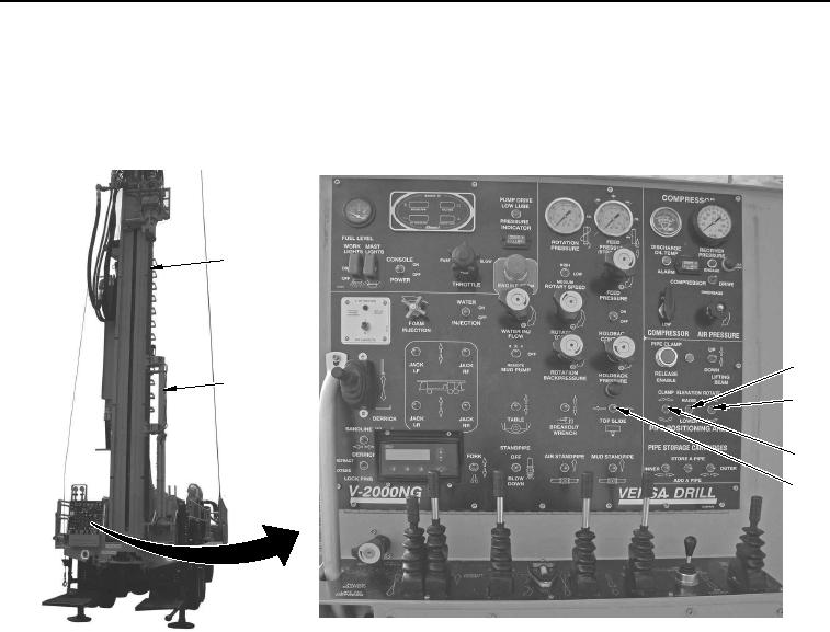
MANUAL SLING LOADING OF DRILL RODS WWDR - Continued
9.
Set and hold PIPE POSITIONING ARM ELEVATION switch (Figure 6, Item 3) to RAISE position to lift
automated drill rod handling arm (Figure 6, Item 2).
1
3
2
4
5
6
WWDS00691
Figure 6.
Automated Drill Rod Handling Arm Raised.
10.
Set PIPE POSITIONING ARM ROTATE switch (Figure 6, Item 4) left position to turn automated drill rod
handling arm (Figure 6, Item 2) inward.
NOTE
Ensure tophead is at top of mast.
11.
Set TOP SLIDE switch (Figure 6, Item 6) to right position to place upper drill rod (Figure 6, Item 1) in
automated drill rod handling arm (Figure 6, Item 2).
12.
Set and hold PIPE POSITIONING ARM CLAMP switch (Figure 6, Item 5) to up position to secure upper drill
rod (Figure 6, Item 1).