
TM 5-3820-276-10-1
0026
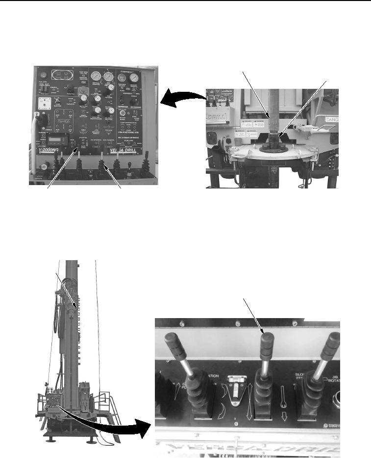
MANUAL SLING LOADING OF DRILL RODS WWDR - Continued
7.
Push ROTATION control lever (Figure 4, Item 4) and FAST FEED control lever (Figure 4, Item 3) forward to
spin and raise upper drill rod (Figure 4, Item 1) free of lower drill rod (Figure 4, Item 2).
1
2
3
4
WWDS00636
Figure 4.
Drill Rod Separation.
8.
Continue pushing FAST FEED control lever (Figure 5, Item 2) forward to raise tophead (Figure 5, Item 1) to
top.
1
2
WWDS00637
Figure 5.
Tophead Raised.