
TM 5-3820-276-10-1
0026
MANUAL SLING LOADING OF DRILL RODS WWDR - Continued
1
2
3
5
4
WWDS00634
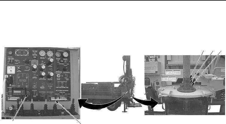
Figure 2.
Fork Switch Operation.
3.
Pull SLOW FEED control lever (Figure 2, Item 4) back and lower the lower drill rod (Figure 2, Item 1) until
top of tooling joint (Figure 2, Item 2) is approximately 0.5 in. (13 mm) above top of fork (Figure 2, Item 3).