
TM 5-3820-276-10-1
0026
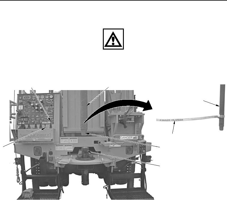
MANUAL SLING LOADING OF DRILL RODS WWDR - Continued
WARNING
Make sure only authorized personnel are present for operation. Failure to comply may
result in injury or death to personnel. Seek medical attention in the event of an injury.
19.
With aid of an assistant, push main winch control lever (Figure 10, Item 1) forward to raise drill rod
(Figure 10, Item 2).
1
2
2
3
6
4
3
5
WWDS00695
Figure 10. Drill Rod Alignment.
CAUTION
Ensure jib line is free of obstructions before turning jib. Failure to comply may result in
damage to equipment.
20.
With aid of an assistant, push JIB ROTATE/RAISE/LOWER control lever (Figure 10, Item 6) left to move
upper drill rod (Figure 10, Item 2) over lower drill rod (Figure 10, Item 5).
21.
Remove bottom end cap (Figure 10, Item 4) from upper drill rod (Figure 10, Item 2).
22.
Pull JIB ROTATE/RAISE/LOWER control lever (Figure 10, Item 6) back and lower upper drill rod
(Figure 10, Item 2) to lower drill rod (Figure 10, Item 5).
23.
Remove 8-ft nylon web sling (Figure 10, Item 3) from end of upper drill rod (Figure 10, Item 2).
24.
Apply antiseize compound to threads of upper drill rod (Figure 10, Item 2).
02/13/2013root(opusualwp)wpno(O10011)