
TM 5-3820-276-10-1
0026
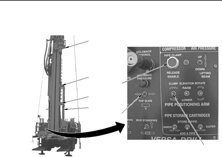
MANUAL SLING LOADING OF DRILL RODS WWDR - Continued
35.
Push and hold PIPE CLAMP RELEASE ENABLE button (Figure 15, Item 6).
1
2
6
2
3
5
4
WWDS00453
Figure 15. Drill Rod Release.
36.
Set PIPE POSITIONING ARM CLAMP switch (Figure 15, Item 4) in down position to release clamps
(Figure 15, Items 2) of automated drill rod handling arm (Figure 15, Item 3).
37.
Set TOP SLIDE switch (Figure 15, Item 5) in left position to move tophead (Figure 15, Item 1) and upper drill
rod (Figure 16, Item 1) over lower drill rod (Figure 16, Item 2).
02/13/2013root(opusualwp)wpno(O10011)