
TM 5-3820-276-10-1
0026
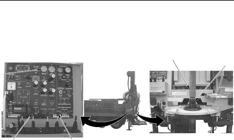
MANUAL SLING LOADING OF DRILL RODS WWDR - Continued
38.
Pull SLOW FEED control lever (Figure 16, Item 3) back and engage drill bit assembly (Figure 16, Item 2).
1
2
5
3
4
WWDS00645
Figure 16. Drill Rods Attached.
39.
Pull SLOW FEED control lever (Figure 16, Item 3) and ROTATION control lever (Figure 16, Item 4) back to
lower and spin upper drill rod (Figure 16, Item 1) until ROTATION PRESSURE gauge (Figure 16, Item 5)
reads 2,100 psi (145 bar).
40.
Repeat Steps 1 through 38 to manually sling load sufficient drill rod to achieve depth required.
END OF TASK
02/13/2013root(opusualwp)wpno(O10011)