
TM 5-3820-276-10-1
0026
MANUAL SLING LOADING OF DRILL RODS WWDR - Continued
WARNING
Make sure hoist plug swivels freely, without loosening connection, when attached to drill
rod. Failure to comply may result in injury or death to personnel. Seek medical attention in
the event of an injury.
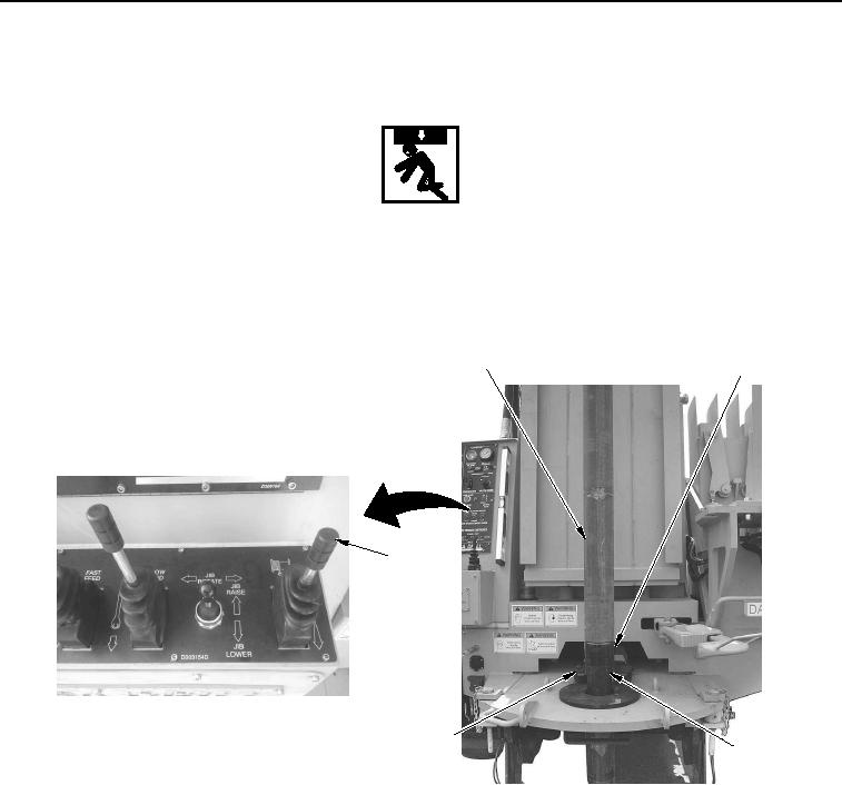
25.
Pull main winch control lever (Figure 11, Item 5) back to lower upper drill rod (Figure 11, Item 1) until
threads enter lower drill rod (Figure 11, Item 2).
1
2
5
4
3
WWDS00643
Figure 11. Drill Rod Connection.
26.
Install upper drill rod (Figure 11, Item 1) to lower drill rod (Figure 11, Item 2) and tighten.
27.
Push main winch control lever (Figure 11, Item 5) forward to raise lower drill rod (Figure 11, Item 2) up until
top of tooling joint (Figure 11, Item 3) is approximately 0.5 in. (13 mm) above top of fork (Figure 11, Item 4).
02/13/2013root(opusualwp)wpno(O10011)