
TM 5-3820-276-10-1
0026
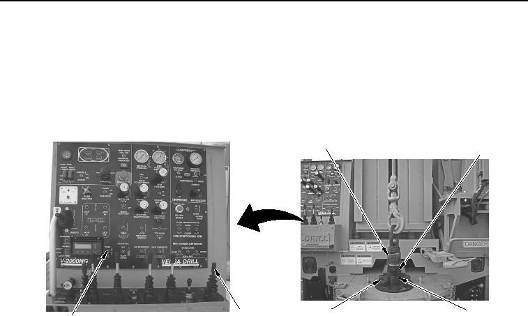
MANUAL SLING LOADING OF DRILL RODS WWDR - Continued
28.
Set FORK switch (Figure 12, Item 6) to position up to retract fork (Figure 12, Item 4).
1
2
4
3
5
6
WWDS00644
Figure 12. Fork Switch.
29.
Pull main winch control lever (Figure 12, Item 5) back to lower upper drill rod (Figure 12, Item 2) until top of
tooling joint (Figure 12, Item 3) is approximately 0.5 in. (13 mm) above top of fork (Figure 12, Item 4).
30.
Set and hold FORK switch (Figure 12, Item 6) to down position to extend fork
(Figure 12, Item 4).
31.
Remove hoist plug (Figure 12, Item 1) from upper drill rod (Figure 12, Item 2).
02/13/2013root(opusualwp)wpno(O10011)