
TM 5-3820-276-10-1
0031
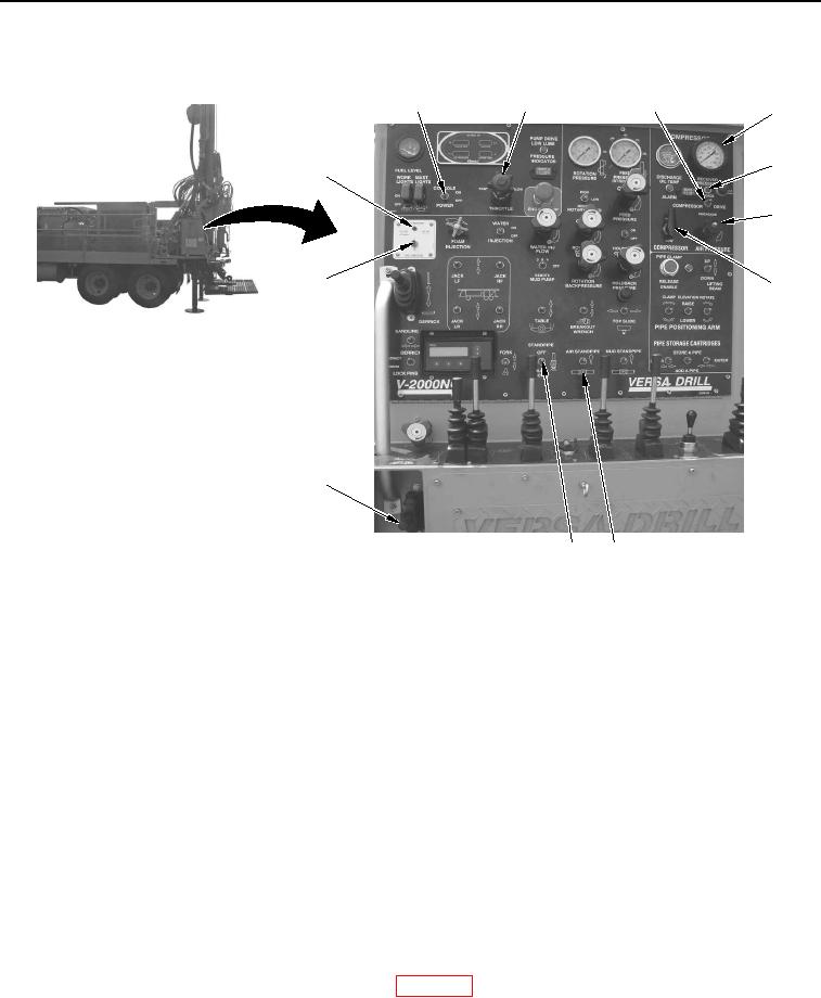
TRUCK MOUNTED AIR COMPRESSOR/LUBRICATOR ASSEMBLY OPERATION DRILLING OPERATIONS
- Continued
1
2
3
4
5
12
6
11
7
10
9
8
WWDS00714
Figure 3.
Console Panel Controls.
14.
Set AIR STANDPIPE switch (Figure 3, Item 8) down to stop air flow to tophead.
15.
Rotate COMPRESSOR HIGH/LOW knob (Figure 3, Item 7) to LOW position.
16.
Rotate AIR PRESSURE knob (Figure 3, Item 6) counterclockwise to until RECEIVER PRESSURE gauge
(Figure 1, Item 4) indicates a decrease in air pressure.
17.
Lift and hold TRUCK CLUTCH control lever (Figure 3, Item 10) to disengage truck clutch.
18.
Set COMPRESSOR DRIVE ENGAGE/DISENGAGE switch (Figure 3, Item 3) down to DISENGAGE
position. Compressor drive disconnect engaged indicator light (Figure 3, Item 5) will go out.
19.
Release TRUCK CLUTCH control lever (Figure 3, Item 10).
20.
Set AIR STANDPIPE switch (Figure 3, Item 8) to down position and hold until valve is fully closed.
21.
Set STANDPIPE switch (Figure 3, Item 9) down to BLOW DOWN position and hold until valve is fully
opened.
22.
Adjust THROTTLE (Figure 3, Item 2) to decrease engine speed to approximately 700 rpm.
23.
Set CONSOLE POWER ON/OFF switch (Figure 3, Item 1) to OFF position.
24.
Perform post operation of drilling rig as required (WP 0029).
END OF TASK