
TM 5-3820-276-10-1
0045
GENERATOR OPERATION - Continued
WARNING
Do not attempt to perform any maintenance tasks on the generator during operation.
Serious electrical shock or death by electrocution may result. Failure to comply may result
in injury or death to personnel. Seek medical attention in the event of an injury.
NOTE
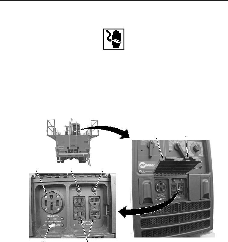
Power is now available for use at auxiliary power receptacles in the lower control panel.
6.
Open auxiliary lower control panel door (Figure 4, Item 4) to access the 120/240V receptacle
(Figure 4, Item 1) and 50 A MAIN BREAKER (CB1) ON/OFF switch (Figure 4, Item 7), and/or auxiliary lower
control panel door (Figure 4, Item 5) to access two 120V receptacles (Figure 4, Item 6) and supplementary
protectors CB2 and CB3 (Figure 4, Items 2 and 3).
4
5
1
2
3
7
6
WWDS00219
Figure 4.
Lower Control Panel.
END OF TASK