
TM 5-3825-270-23&P
FIELD MAINTENANCE
3" VALVE REPLACEMENT
INITIAL SETUP:
Tools and Special Tools
References
Tool Kit, General Mechanic's: Automotive
Parts Manual (WP 0220) Figure 4007
(WP 0225, Table 1, Item 12)
Equipment Condition
Materials/Parts
Valve handle removed. (WP 0180)
Locknut (WP 0226, Table 1, Item 64) Qty: 8
Gasket (WP 0226, Table 1, Item 35) Qty: 2
REMOVAL
NOTE
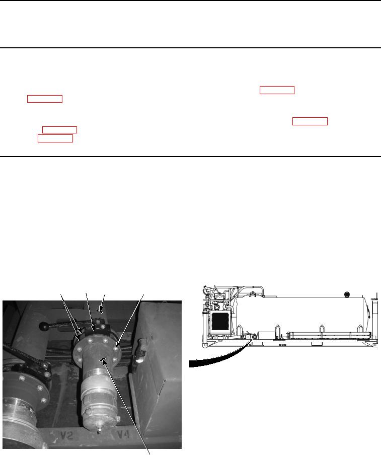
All 3" valves are removed the same way. Valve V4 shown.
Some valves may have other components that have to be removed or supported during
valve replacement. Remove or support other components as necessary.
Note position of valve assembly prior to removal, to ensure proper installation.
Remove eight locknuts (Figure 1, Item 4), adapter pipe (Figure 1, Item 6), gasket (Figure 1, Item 1), valve
(Figure 1, Item 2), gasket (Figure 1, Item 1), and screws (Figure 1, Item 5) from water tank assembly (Figure
1, Item 3). Discard locknuts.
1
2
3
4, 5
6
Figure 1. 3" Valve Removal.
END OF TASK