
TM 5-3825-270-23&P
0159
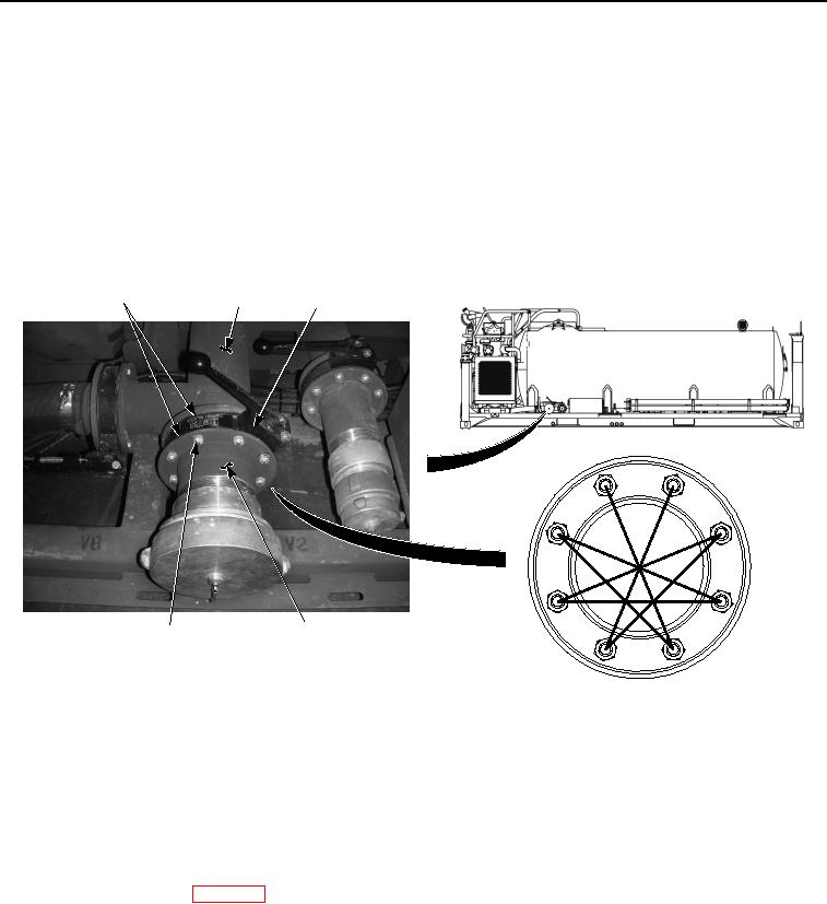
INSTALLATION
NOTE
All 5" valves are installed the same way. Valve V2 shown.
Some valves may have other components that have to be removed or supported during
valve replacement. Remove or support other components as necessary.
Position as noted prior to removal.
1.
Install gasket (Figure 2, Item 1), valve (Figure 2, Item 3), gasket (Figure 2, Item 1), and adapter pipe (Figure
2, Item 4) on water tank assembly (Figure 2, Item 2) with eight screws (Figure 2, Item 6) and locknuts (Figure
2, Item 5).
1
2
3
1
8
3
6
4
5
4
5, 6
7
2
TIGHTENING SEQUENCE
Figure 2. 5" Valve Installation.
2.
Tighten locknuts (Figure 2, Item 5) in sequence shown.
END OF TASK
FOLLOW-ON MAINTENANCE
Install valve handle. (WP 0180)
END OF TASK
END OF WORK PACKAGE