
TM 5-3825-270-23&P
FIELD MAINTENANCE
GOVERNOR ACTUATOR REPLACEMENT
INITIAL SETUP:
Tools and Special Tools
References
Tool Kit, General Mechanic's: Automotive
Parts Manual (WP 0220) Figure 4026
(WP 0225, Table 1, Item 12)
Equipment Condition
Batteries disconnected. (WP 0085)
Materials/Parts
Compound, Sealing (WP 0224, Table 1, Item 18)
Rear access panel removed. (TM 5-3825-270-10).
REMOVAL
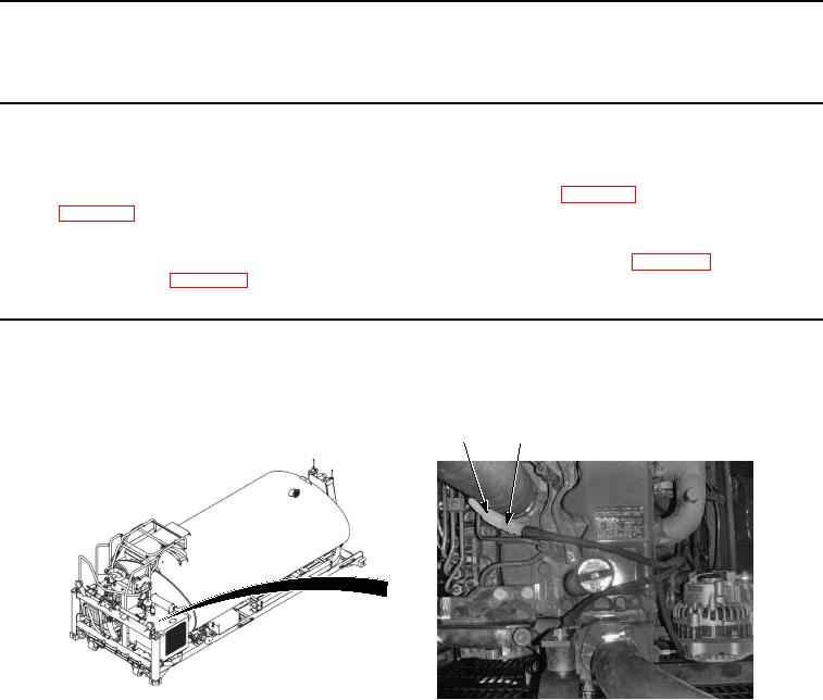
1.
Disconnect connector (Figure 1, Item 1) from connector (Figure 1, Item 2).
1
2
1
Figure 1. Governor Actuator Removal.
CAUTION
Do not allow dirt, or debris fall into injection pump when removing governor actuator. Failure
to comply may result in damage to equipment.
2.
Remove two hex screws (Figure 2, Item 5) and governor actuator (Figure 2, Item 3) from injection pump (Figure
2, Item 4).