
TM 5-3825-270-23&P
0131
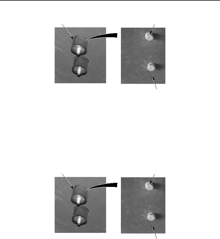
REMOVAL - Continued
15
21, 22
23
Figure 3. Glow Plug Relay Removal.
END OF TASK
INSTALLATION
NOTE
Perform Step (1) if isolators were removed.
All isolators are installed the same way. Top isolator shown.
1.
Install isolator (Figure 4, Item 15) on mounting surface (Figure 4, Item 23) with lockwasher (Figure 4, Item 22)
and screw (Figure 4, Item 21).
15
21, 22
23
Figure 4. Glow Plug Relay Installation.
2.
Install glow plug relay (Figure 5, Item 16) on isolators (Figure 5, Item 15) with lockwashers (Figure 5, Item 14)
and nuts (Figure 3, Item 13).