
TM 5-3825-270-23&P
0032
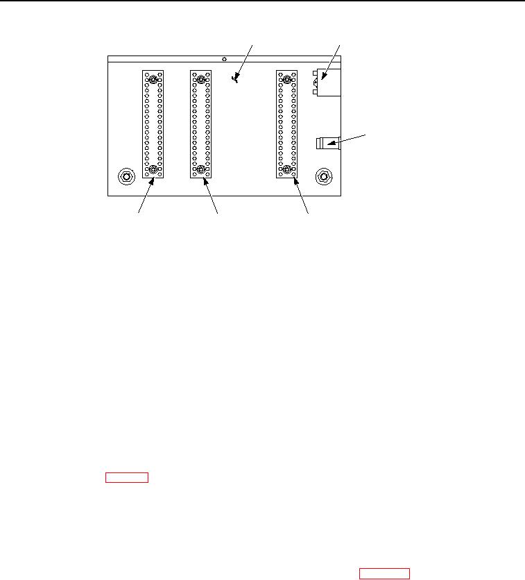
INSIDE OF
15-AMP
CONTROL PANEL
CIRCUIT BREAKER
20
1
1
15
5
5
EMERGENCY
10
10
10
STOP SWITCH
5
15
15
1
20
20
INTERCONNECT
POSITIVE
NEGATIVE
TERMINAL STRIP
TERMINAL STRIP
TERMINAL STRIP
Figure 2. Interconnect Terminal Strip - Step 2.
6.
Set multimeter to measure continuity.
NOTE
This test is checking for a short in the wiring harness. Continuity should not be present on
wire(s) being tested to ground. If continuity is present, a short to ground condition exists.
7.
Connect red multimeter probe to disconnected black wire at interconnect terminal strip, terminal 10.
8.
Connect black multimeter probe to known good ground.
9.
Note multimeter reading.
CONDITION/INDICATION
Are greater than 10,000 ohms measured on black wire from interconnect terminal strip, terminal 10 to known
good ground?
DECISION
No - Repair or replace black wire from interconnect terminal strip, terminal 10 to governor controller harness
connector, pin B3. (WP 0099) Verify problem is solved. (Step 4 - Does ENGINE OFF/BATTERY DRAIN indicator
turn off normally?)
Yes - Go to step 3. (Step 3 - Are greater than 10,000 ohms measured on white/red wire at interconnect terminal
strip, terminal 10 to known good ground?)
STEP 3
Are greater than 10,000 ohms measured on white/red wire at interconnect terminal strip, terminal 10 to
known good ground?
1.
Reconnect governor controller harness connector to governor controller. (WP 0092)
2.
Reconnect black wire to interconnect terminal strip terminal 10.