
TM 5-3825-270-23&P
0028
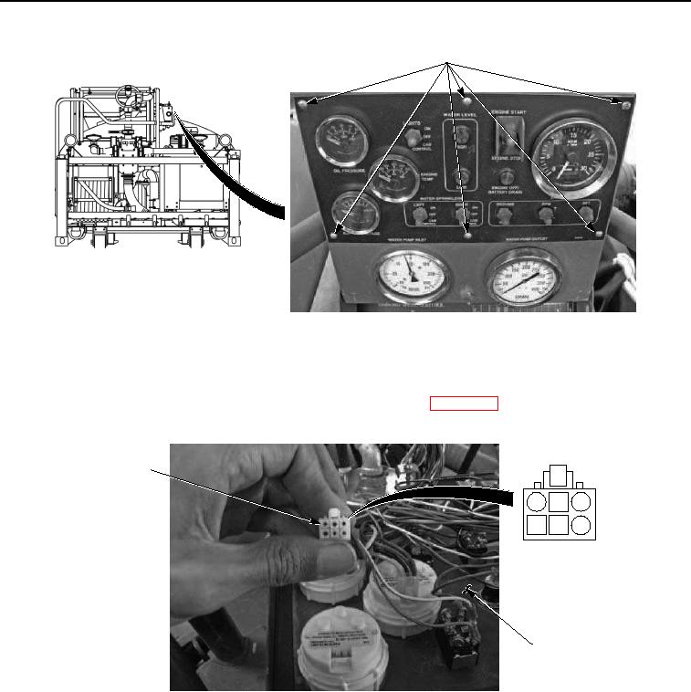
CONTROL PANEL
FACEPLATE SCREWS
Figure 2. Control Panel Faceplate Screws - Step 2.
3.
Set multimeter to measure voltage.
4.
Rotate EMERGENCY STOP switch to on position. (TM 5-3825-270-10)
5.
Disconnect harness connector from BATTERY VOLTAGE gauge. (WP 0087)
6.
Connect red multimeter probe to BATTERY VOLTAGE harness connector, pin 6.
GAUGE
HARNESS
CONNECTOR
1
2
3
4
5
6
BACK OF
CONTROL PANEL
Figure 3. Gauge Harness Connector - Step 2.
7.
Connect black multimeter probe to known good ground.
8.
Note multimeter reading.
9.
Push in EMERGENCY STOP switch to off position. (TM 5-3825-270-10)
CONDITION/INDICATION
Are 22 to 28 VDC present at BATTERY VOLTAGE gauge harness connector, pin 6?