
TM 5-3825-270-23&P
0027
WARNING
Ensure electrical power is off prior to working on all electrical systems. Failure to comply
may result in injury or death to personnel.
Remove all jewelry, such as rings, ID tags, bracelets, etc., prior to working on or around
equipment. Jewelry and tools can catch on equipment, contact positive electrical circuits,
and cause a direct short, severe burns, or electrical shock. Failure to comply may result
in injury or death to personnel.
2.
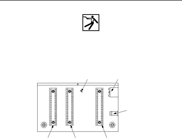
Connect red multimeter probe to negative terminal strip, terminal 6.
INSIDE OF
15-AMP
CONTROL PANEL
CIRCUIT BREAKER
20
1
1
15
5
5
EMERGENCY
10
10
10
STOP SWITCH
5
15
15
1
20
20
POSITIVE
NEGATIVE
INTERCONNECT
TERMINAL STRIP
TERMINAL STRIP
TERMINAL STRIP
Figure 9. Negative Terminal Strip - Step 8.
3.
With the aid of an assistant, connect black multimeter lead to negative battery terminal.