
TM 5-3820-276-10-2
0203
Table 1.
PMCS - Grouter - Before Drilling Equipment Operation - Continued.
ITEM TO BE
EQUIPMENT
ITEM
CHECKED OR
NOT READY/
NO.
INTERVAL
SERVICED
PROCEDURE
AVAILABLE IF:
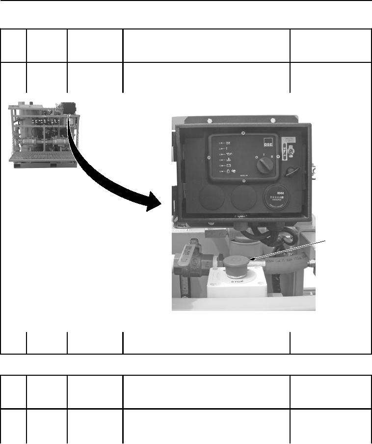
2. Check EMERGENCY STOP button (Figure 22, Item
Engine does not shut off.
1) for proper operation. Push in EMERGENCY STOP
Notify maintenance.
button.
1
WWDS00581
Figure 22. Emergency Stop Button.
3. Reset EMERGENCY STOP button (Figure 22, Item
1).
Table 2.
PMCS - Grouter - During Drilling Equipment Operation.
ITEM TO BE
EQUIPMENT
ITEM
CHECKED OR
NOT READY/
NO.
INTERVAL
SERVICED
PROCEDURE
AVAILABLE IF:
1
During
Fault Indicators
1. Start grouter (Volume 1, WP 0040).
2. Check auxiliary alarm indicator (Figure 23, Item 1).
LED status indicator on.
Notify maintenance.
02/13/2013root(pmcswp)wpno(I20003)