
TM 5-3820-276-10-1
0042
GROUTER POST OPERATION - Continued
NOTE
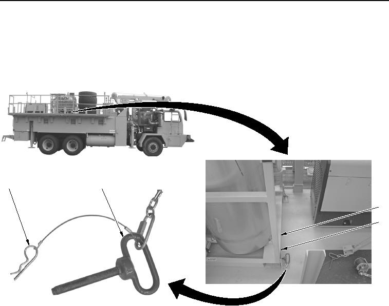
There are four mount pins and safety pins but only two are shown.
6.
Install four mount pins (Figure 5, Item 2) to grouter frame (Figure 5, Item 3) and WWSV brackets
(Figure 5, Item 4).
2
1
3
4
WWDS00383
Figure 5.
Mount Pin Installation.
7.
Install four safety pins (Figure 5, Item 1) to mount pins (Figure 5, Item 2).
8.
Remove two lifting straps (Figure 6, Item 2) from grouter lifting rings (Figure 6, Item 3) and crane hook
(Figure 6, Item 1).