
TM 5-3820-276-10-1
0024
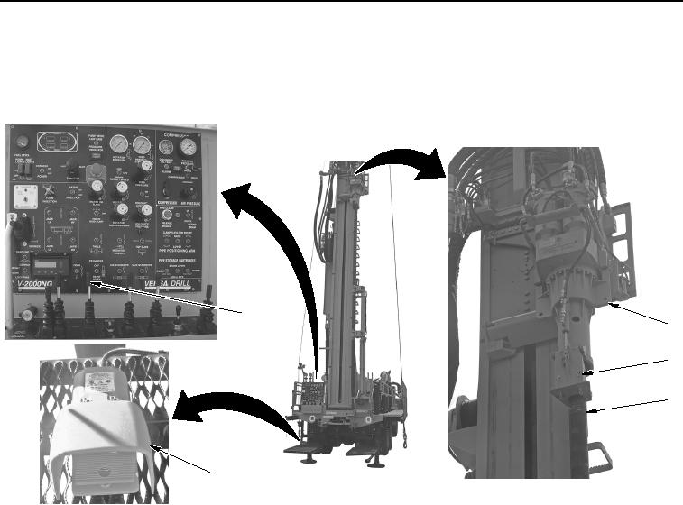
STORING DRILL ROD WITH PENDANT - Continued
5.
Push foot switch (Figure 38, Item 4) with foot to engage tophead mounted wrench (Figure 38, Item 2) on drill
rod (Figure 38, Item 3).
5
1
2
3
4
WWDS00491
Figure 38. Tophead Mounted Wrench Operation.
6.
Push ROTATION control (Figure 38, Item 5) forward to break joint from tophead (Figure 38, Item 1) to drill
rod (Figure 38, Item 3).
7.
Release foot switch (Figure 38, Item 4) once joint has been broken.
8.
Push ROTATION control (Figure 39, Item 5) and FAST FEED control (Figure 39, Item 4) forward at same
time to disconnect tophead (Figure 39, Item 1) from drill rod (Figure 39, Item 2).
02/13/2013root(opusualwp)wpno(O10010)