
TM 5-3820-276-10-1
0024
STORING DRILL ROD WITH PENDANT - Continued
13.
Push and hold PIPE ARM CLAMP switch (Figure 40, Item 9) in down position and depress PIPE CLAMP
RELEASE ENABLE button (Figure 40, Item 1) to open clamps (Figure 40, Item 5) and release drill rod
(Figure 40, Item 4).
14.
Set and hold PIPE ARM ELEVATION switch (Figure 40, Item 7) up in RAISE position to move automated
rod handling arm (Figure 40, Item 3) to upright position.
15.
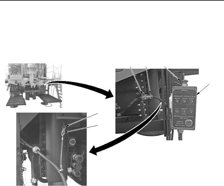
Push POWER switch (Figure 41, Item 3) in on pendant (Figure 41, Item 4) to turn power off.
1
2
3
4
5
6
WWDS00462
Figure 41. Drill Rod Handling System Pendant Removal.
16.
Disconnect pendant connector (Figure 41, Item 2) from WWDR connector (Figure 41, Item 1).
17.
Remove safety lanyard (Figure 41, Item 6) from eyebolt (Figure 41, Item 5).
18.
Install cap (Figure 42, Item 2) to WWDR connector (Figure 42, Item 1).
02/13/2013root(opusualwp)wpno(O10010)