TM 5-4320-300-14
6-11. CRANKSHAFT AND FLYWHEEL (CONT)
Location/Item
Action
Remarks
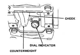
63. Crankshaft
Rotate crankshaft clockwise
counterweight
until crankshaft counter-
check
weights at rear connecting
rod journal are in the
6 o'clock position. Center
punch a hole in the inside
face of each counterweight
cheek, 1/4 inch (6.35 mm)
from lower end of each
counterweight. Install a
dial gage in center punch
holes in cheek of each
counterweight. Set dial in-
dicator at zero. Rotate the
crankshaft to the 3 and 9 o'clock positions.
Note indicator readings at the 3, 6, and
9 o'clock counterweight positions. The maxi-
mum allowable variation is 0.0045 inch
(0.1143 mm) total indicator reading.
CAUTION
Equipment damage due to crankshaft distortion may occur if flexible coupling is misaligned
during installation. Install coupling on engine carefully.
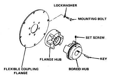
64. Flexible
Position flange, flange hub, bored hub, set
coupling
screw, and key as a unit against the flywheel.
Install flange mounting bolts and lockwashers.
Tighten bolts securely.
6-114