TM 5-4320-300-14
6-12. BEARINGS (CONT)
Location/Item
Action
Remarks
b. Rotate crankshaft about 30 degrees from
bottom dead center; then install lower
bearing shells and caps.
NOTE
Bolts will seat better if bolt caps are rapped sharply with a soft hammer after being installed hand
tight.
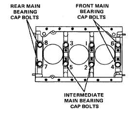
c. Torque front and intermediate main bear-
ing cap bolts to 120 to 130 ft lb (163 to
176 N.m), in an alternating pattern as
shown.
d. Torque rear main bearing cap bolts to 40 to
50 foot pounds (54 to 68 N.m).
e. Remove all bearing cap bolts and caps. Use
lifting device to remove crankshaft, and re-
move the flattened plastic strip.
f. Compare width of flattened plastic strip at
its widest point with graduations on envelope
gage to determine clearance encountered. The
number within the graduation on the envelope
indicates bearing clearance in thousandths of
an inch.
9.
Clearance
The clearance between a crankshaft journal and
limits
its bearing shell should be not greater than 0.006
inch (0.1524 mm). Replace all bearing shells if
any must be replaced.
6-118