
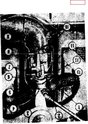
TM 5-4320-218-15
the lever so that the choke is open
(1) ; secure the carburetor to the mani-
wide, and with the choke control on
fold with two cap screws (3) and lock-
washers (4). Be sure that all the
the front panel all the way in, tighten
mounting surfaces are clean.
the choke swivel screw (8).
(2) Remove the seal from the fuel line
(4) Install the air-cleaner hose.
(6) ; connect the line to the carbure-
(5) Attach the governor control rod (11)
tor. Take care that dirt or foreign
to the throttle shaft assembly and stop
matter does not enter the fuel system.
lever (2). Adjust the length of the
(3) Insert the choke control wire (9) in
rod (par. 57b).
the hole of the choke lever. Operate
1
Intake manifold
2
Throttle shaft assembly and stop lever
Cap screw
3
Lockwasher
4
Flange gasket
5
Fuel line
6
Idle adjusting screw
7
Choke swivel screw
8
Choke control wire
9
Cotter pin
10
Governor control rod
11
Throttle adjusting screw
12
Throttle adjusting screw spring
13
Carburetor installation
37