
TM 5-3825-270-23&P
0199
REMOVAL - Continued
28
30
29
7
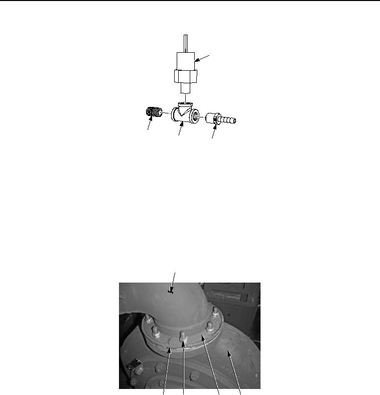
Figure 6. Discharge Tube and Pipe Assembly Pump Outlet Hose Removal.
13.
Remove pressure sending unit (Figure 6, Item 28) from fitting (Figure 6, Item 29).
14.
Remove fitting (Figure 6, Item 30) from fitting (Figure 6, Item 29).
END OF TASK
INSTALLATION
1.
Install discharge tube (Figure 7, Item 4) on water pump (Figure 7, Item 9) with gasket (Figure 7, Item 27), two
flange reinforcement plates (Figure 7, Item 25) and eight locknuts (Figure 7, Item 26).
4
27
26
25
9
Figure 7. Discharge Tube and Pipe Assembly Pump Outlet Hose Installation.
2.
Install support bracket (Figure 8, Item 16) on water pump (Figure 8, Item 9) and flywheel housing (Figure 8,
Item 15) with two washers (Figure 8, Item 14) and screws (Figure 8, Item 13).