
TM 5-3825-270-23&P
0136
INSTALLATION - Continued
1
2
3
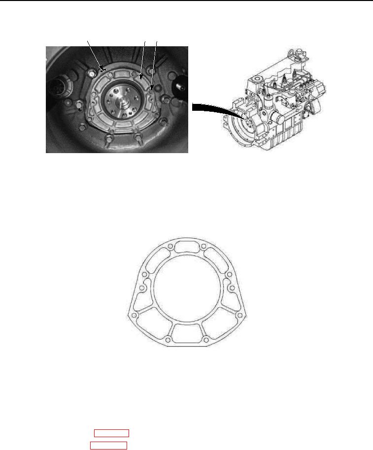
Figure 10. Rear Main Seal Installation.
CAUTION
Rear main seal housing assembly screws must be tightened evenly, in sequence shown.
Failure to comply may result in an oil leak and damage to equipment.
7.
Torque screws to 18-20 lb ft (24-27 Nm).
3
5
7
1
2
8
6
4
TIGHTENING SEQUENCE DIAGRAM
Figure 11. Rear Main Seal Installation.
END OF TASK
FOLLOW-ON MAINTENANCE
1.
Install engine flywheel. (WP 0112)
2.
Install engine module. (WP 0128)
END OF TASK
END OF WORK PACKAGE