
TM 5-3825-270-23&P
0102
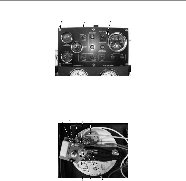
REMOVAL - Continued
5
6
3, 4
Figure 2. Main Control Panel Tachometer/Hourmeter Removal.
NOTE
Tag and mark wires prior to removal to ensure proper installation.
3.
Remove nut (Figure 3, Item 15), washer (Figure 3, Item 16), and two black wires (Figure 3, Item 13) from
ground stud (Figure 3, Item 14).
7
8
9
10 11, 12
15, 16 14
13
Figure 3. Main Control Panel Tachometer/Hourmeter Removal.
4.
Remove nut (Figure 3, Item 7), white wire (Figure 3, Item 9), and red wire (Figure 3, Item 10) from +24 vdc
stud (Figure 3, Item 8).
5.
Disconnect yellow wire (Figure 3, Item 11) from terminal (Figure 3, Item 12).
6.
Remove nut (Figure 4, Item 22), lockwasher (Figure 4, Item 23), washer (Figure 4, Item 24), and grey wire
(Figure 4, Item 17) from stud (Figure 4, Item 21). Discard lockwasher.