
TM 5-3825-270-23&P
0102
REMOVAL - Continued
17
14 18 19
20
21
22, 23, 24
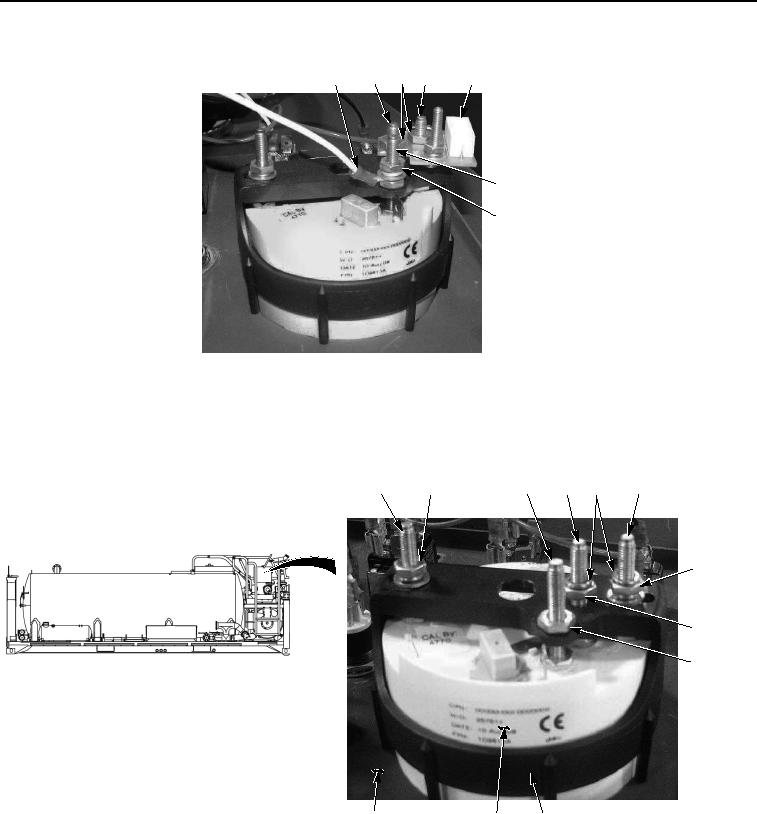
Figure 4. Main Control Panel Tachometer/Hourmeter Removal.
7.
Remove two nuts (Figure 4, Item 18) and circuit board (Figure 4, Item 20) from stud (Figure 4, Item 14) and
stud (Figure 4, Item 19).
8.
Remove two lockwashers (Figure 5, Item 29) from stud (Figure 5, Item 14) and stud (Figure 5, Item 19).
25
26, 27, 28
21
14
29
19
30, 31, 33
33
34
6
36
35
Figure 5. Main Control Panel Tachometer/Hourmeter Removal.
9.
Remove nut (Figure 5, Item 33) from stud (Figure 5, Item 14).
10.
Remove nut (Figure 5, Item 34) from stud (Figure 5, Item 21).
11.
Remove nut (Figure 5, Item 30), lockwasher (Figure 5, Item 31), and washer (Figure 5, Item 32) from stud
(Figure 5, Item 19).