
TM 5-3825-270-23&P
0040
DECISION
No - Repair or replace black/red wire between engine RESUME/IDLE switch and interconnect terminal strip,
terminal 2. (WP 0099) Verify problem is solved. (Step 7 - Does engine RESUME/IDLE switch operate
normally?)
Yes - Repair or replace black wire from interconnect terminal strip, terminal 2 to governor controller harness
connector, pin B1. (WP 0099) Verify problem is solved. (Step 7 - Does engine RESUME/IDLE switch operate
normally?)
STEP 6
Are less than 200 ohms measured from red/black wire on engine RESUME/IDLE switch to interconnect
terminal strip, terminal 3?
1.
Ensure multimeter is set to measure continuity.
2.
Connect red multimeter probe to red/black wire on engine RESUME/IDLE switch.
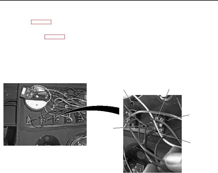
BACK OF
RED/BLACK
PANEL
WIRE
ENGINE
RESUME/IDLE
SWITCH
RED
WIRE
BLACK/RED
WIRE
Figure 11. Engine Resume/Idle Switch - Step 6.
3.
Connect black multimeter probe to interconnect terminal strip, terminal 3.