
TM 5-3825-270-23&P
0006
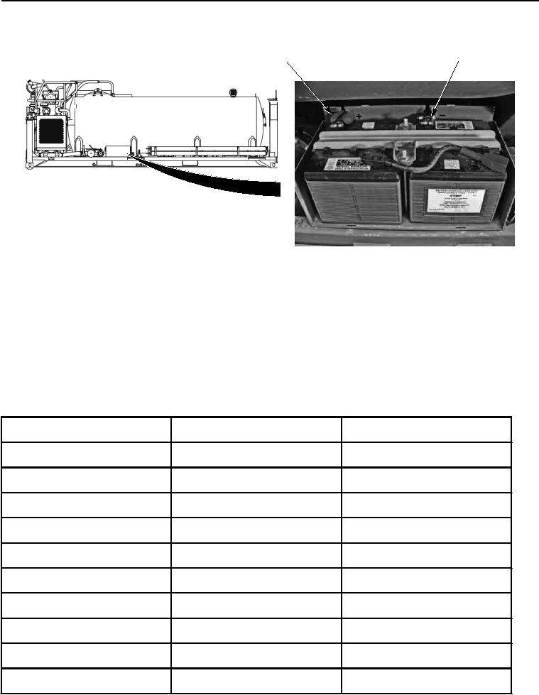
POSITIVE
NEGATIVE
BATTERY
BATTERY
TERMINAL
TERMINAL
Figure 4. Battery Terminals - Step 4.
4.
Note multimeter reading.
NOTE
The following chart describes battery voltage characteristics when measured with a
multimeter. This chart can be used to further isolate and troubleshoot batteries that may be
cause of problem.
5.
Compare multimeter reading to chart below.
Table 1. Battery State Of Charge Voltage Table.
Percentage Of Full Charge
12 Volt DC System
24 Volt DC System
100%
12.7
25.4
90%
12.6
25.2
80%
12.5
25
70%
12.3
24.6
60%
12.2
24.4
50%
12.1
24.2
40%
12.0
24
30%
11.8
23.6
20%
11.7
23.4
10%
11.6
23.2