
TM 5-3820-276-10-2
0201
Table 4.
PMCS - PAC - Before Drilling Equipment Operation - Continued.
ITEM TO BE
EQUIPMENT
ITEM
CHECKED OR
NOT READY/
NO.
INTERVAL
SERVICED
PROCEDURE
AVAILABLE IF:
400 psi (28 bar). Notify
maintenance.
19
Before
Control Panel
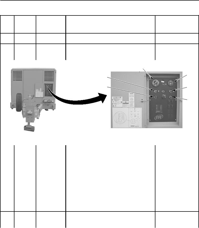
1. Check DISCHARGE AIR PRESSURE gauge (Figure Not between 50 to 80 psi
Gauges
30, Item 1) for proper operation.
(3 to 6 bar) at idle. Notify
maintenance.
1
2
6
5
3
4
WWDS00096
Figure 30. Control Panel Gauges.
2. Check ENGINE SPEED gauge (Figure 30, Item 2)
Not between 1,200 to
for proper operation.
1,500 rpm at idle. Notify
maintenance.
3. Check ENGINE WATER TEMP. gauge (Figure 30,
More than 180F (82C).
Item 3) for proper operation.
Notify maintenance.
4. Check ENGINE OIL PRESS. gauge (Figure 30, Item Less than 18 psi (1 bar).
4) for proper operation.
Notify maintenance.
5. Check VOLTS gauge (Figure 30, Item 5) for proper
Not showing a charge of
operation.
22 to 28 VDC. Notify
maintenance.
6. Check DISCHARGE AIR TEMP. gauge (Figure 30,
More than 150F (66C).
Item 6) for proper operation.
Notify maintenance.
20
Before
Fuel Level
Check FUEL LEVEL gauge (Figure 31, Item 1). Add
clean JP-8/DF2 diesel fuel as required (Volume 1,
WP 0056).
02/13/2013root(pmcswp)wpno(I30001)