
TM 5-3820-276-10-1
0069
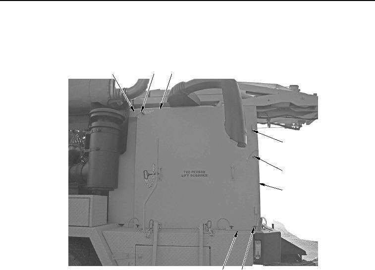
CAB PROTECTION KIT REMOVAL - Continued
7.
Remove forward lockpin (Figure 10, Item 5) from cab protection kit right-side panel (Figure 10, Item 3) and
cab protection kit front panel (Figure 10, Item 6).
1
2
3
4
5
6
8
7
WWDS00660
Figure 10. Cab Protection Kit Right-Side Panel Removal.
8.
Remove upper rear lockpin (Figure 10, Item 2) from cab protection kit right-side panel (Figure 10, Item 3)
and bracket (Figure 10, Item 1).
9.
Remove three lower lockpins (Figure 10, Item 7) from cab protection kit right-side panel (Figure 10, Item 3)
and cab protection kit mounting plate (Figure 10, Item 8).
02/13/2013root(opunuwp)wpno(O00013)