
TM 5-3820-276-10-1
0069
CAB PROTECTION KIT INSTALLATION - Continued
19.
Install forward lockpin (Figure 6, Item 5) to cab protection kit right-side panel (Figure 6, Item 3) and cab
protection kit front panel (Figure 6, Item 8).
20.
If required, push in right-side mirror.
21.
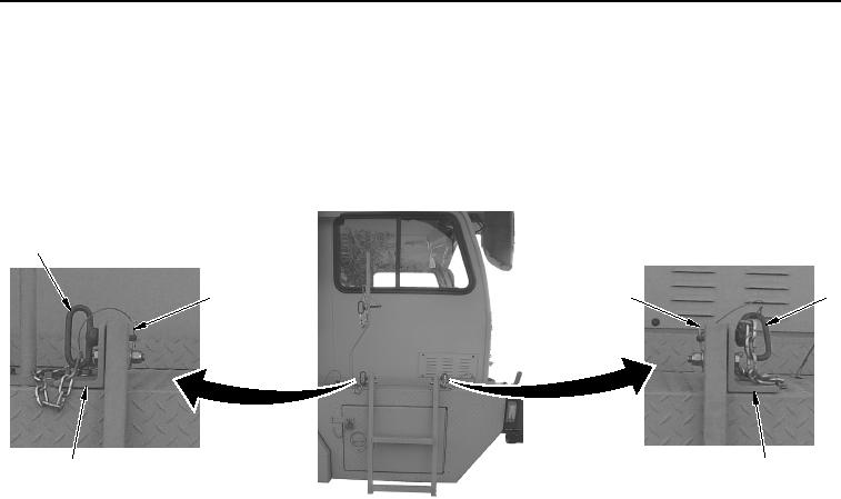
Remove two safety pins (Figure 7, Item 3) from pins (Figure 7, Item 1).
1
1
3
3
2
2
WWDS00656
Figure 7.
Ladder Pin Removal.
22.
Remove two pins (Figure 7, Item 1) from brackets (Figure 7, Item 2).