
TM 5-3820-276-10-1
0069
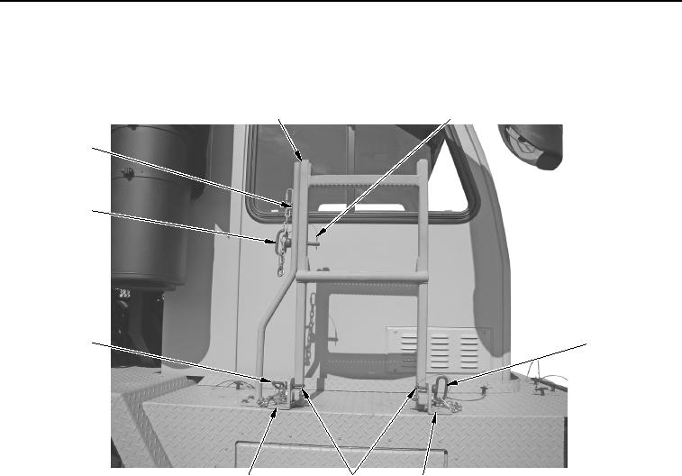
CAB PROTECTION KIT INSTALLATION - Continued
23.
Raise ladder (Figure 8, Item 1) to stowed position.
1
2
7
6
3
3
4
5
4
WWDS00655
Figure 8.
Ladder Stowage.
24.
Install two pins (Figure 8, Item 3) to brackets (Figure 8, Item 4).
25.
Install two safety pins (Figure 8, Item 5) to pins (Figure 8, Item 3).
26.
Install pin (Figure 8, Item 6) to bracket (Figure 8, Item 7) and ladder (Figure 8, Item 1).
27.
Install safety pin (Figure 8, Item 2) to pin (Figure 8, Item 6).
END OF TASK