
TM 5-3820-276-10-1
0069
CAB PROTECTION KIT REMOVAL - Continued
13.
Remove upper rear lockpin (Figure 11, Item 3) from cab protection kit left-side panel (Figure 11, Item 2) and
bracket (Figure 11, Item 4).
NOTE
There are three lower lockpins but only two are shown.
14.
Remove three lower lockpins (Figure 11, Item 5) from cab protection kit left-side panel (Figure 11, Item 2)
and cab protection kit mounting plate (Figure 11, Item 6).
CAUTION
Use care when installing and removing side panels. Panels can damage mirrors. Failure to
comply may result in damage to equipment.
15.
With aid of an assistant, remove cab protection kit left-side panel (Figure 9, Item 2) from tabs
(Figure 11, Item 1) of cab protection kit front panel (Figure 11, Item 8).
16.
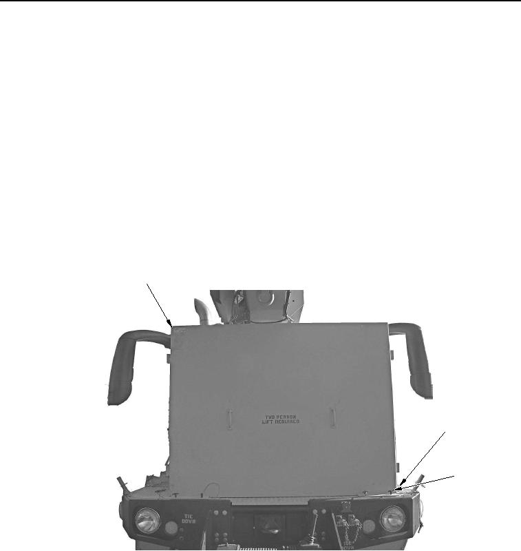
Remove four lockpins (Figure 12, Item 3) from cab protection kit front panel (Figure 12, Item 1) and cab
protection kit mounting plate (Figure 12, Item 2).
1
2
3
WWDS00658
Figure 12. Cab Protection Kit Front Panel Removal.
17.
With aid of an assistant, remove cab protection kit front panel (Figure 12, Item 1) from cab protection kit
mounting plate (Figure 12, Item 2).
02/13/2013root(opunuwp)wpno(O00013)