
TM 5-3820-276-10-1
0069
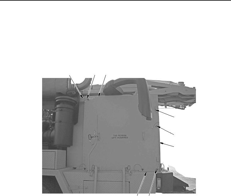
CAB PROTECTION KIT INSTALLATION - Continued
CAUTION
Use care when installing and removing side panels. Panels can damage mirrors. Failure to
comply may result in damage to equipment.
16.
With aid of an assistant, align cab protection kit right-side panel (Figure 6, Item 3) with cutouts over tabs
(Figure 6, Item 4) of cab protection kit front panel (Figure 6, Item 6) and slide cab protection kit right-side
panel (Figure 6, Item 3) down to lock into position.
1
2
3
4
5
6
8
7
WWDS00660
Figure 6.
Cab Protection Kit Right-Side Panel Installation.
17.
Install three lower lockpins (Figure 6, Item 7) to cab protection kit right-side panel (Figure 6, Item 3) and cab
protection kit mounting plate (Figure 6, Item 8).
18.
Install upper rear lockpin (Figure 6, Item 2) to cab protection kit right-side panel (Figure 6, Item 3) and
bracket (Figure 6, Item 1).