
TM 5-3820-276-10-1
0024
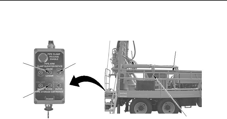
PENDANT OPERATION OF DRILL ROD HANDLING SYSTEM - Continued
9.
Set and hold PIPE ARM ROTATE switch (Figure 29, Item 2) up to turn automated rod handling arm
(Figure 29, Item 3) forward.
3
4
1
2
6
5
WWDS00532
Figure 29. Automated Rod Handling Arm Reload.
10.
Set and hold PIPE STORAGE CARTRIDGES DOWN switch (Figure 29, Item 6) to up position to raise lifting
beam (Figure 29, Item 5) up until next drill rod (Figure 29, Item 4) is in position.
11.
Set and hold PIPE ARM ELEVATION switch (Figure 29, Item 1) down in LOWER position to move
automated rod handling arm (Figure 29, Item 3) down to receive next drill rod (Figure 29, Item 4).
END OF TASK
02/13/2013root(opusualwp)wpno(O10010)