
(4)
Recheck the shaft alignment between the
engine and pump.
If all alignment is
correct, position the coupling halves
together and secure with eight bolts (4, fig.
47 and nuts (6).
102. Assembled Engine, Stub Shaft, and Dash
a. Removal.
(1) Remove the eight bolts (4, fig. 43) and nuts
(6) that secure the coupling halves together.
(2) Remove the side panels and top hood from
the engine (para 99).
(3) Remove the eight engine mounting bolts (5,
fig. 45) and lockwashers that secure the
engine to the skid base. A lifting eye is
provided on one of the cylinder head studs
to facilitate hoisting the engine. Remove
the engine from the skid base.
(4) Pull the coupling hub (3, fig. 43) and key
from the stub shaft on the engine and
remove the coupling half (5) with its
assembled seal (2) and retaining ring (1).
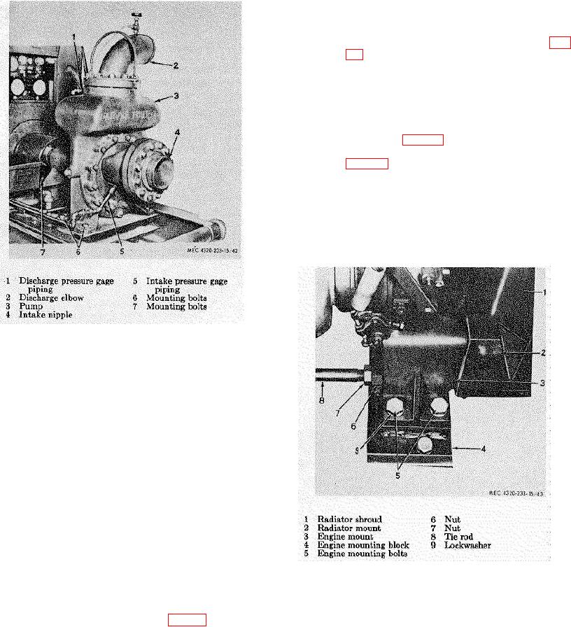
Figure 44. Pump installation.
(4) Remove the coupling hub (3, fig. 43), key,
and coupling half with its assembled seal (2)
and retaining ring (1) from the pump shaft.
b. Cleaning and Inspection.
(1) Clean the outside of the pump with a cloth
dampened with cleaning solvent; wipe dry.
Take care not to let solvent enter the pump.
(2) Inspect the pumpfor cracks, breaks, bent or
scored shaft, or other damage; refer to
higher authority if damaged.
c. Installation.
(1) Position the coupling half (5) with the
assembled seal (2) and retaining ring (1) on
the pump shaft. Position the key in the
keyway of the pump shaft and install the
hub (3) on the shaft.
(2) Position the pump on the skid base. Use a
straightedge to make sure the pump shaft is
Figure 45. Engine mounting.
perfectly aligned with the engine shaft.
Shim under the pump as necessary to
provide correct alignment of the shafts.
(3) Secure the pump to the skid base with six
mounting bolts (6 and 7, fig. 44).
TAGO 6358-A
57