
TM 5-3825-270-23&P
0216
INSTALLATION - Continued
13
3
18
16
20
19
25
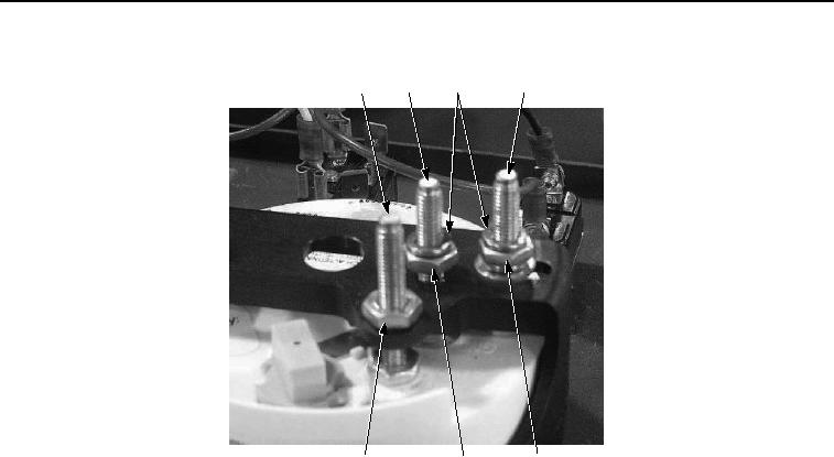
Figure 7. Cab Control Box Tachometer Installation.
NOTE
Install nut and ensure threads showing are same as noted prior to removal.
6.
Install nut (Figure 7, Item 19) on stud (Figure 7, Item 3).
NOTE
Install wires as noted prior to removal.
7.
Install lockwashers (Figure 7, Item 18) on stud (Figure 7, Item 3) and stud (Figure 7, Item 16).
CAUTION
Do not over-tighten nuts on circuit board. Failure to comply will result in damage to equipment.
8.
Install circuit board (Figure 8, Item 17) on stud (Figure 8, Item 3) and stud (Figure 8, Item 16) with nuts (Figure
8, Item 15).