
TM 5-3825-270-23&P
0216
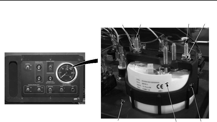
REMOVAL - Continued
16
25, 26,27
21, 22, 23
24
30
29
28
Figure 5. Cab Control Box Tachometer Removal.
10.
Remove nut (Figure 5, Item 25), lockwasher (Figure 5, Item 26), and washer (Figure 5, Item 27) from stud
(Figure 5, Item 16).
NOTE
Note position of tachometer prior to removal to ensure proper installation.
11.
Remove retainer (Figure 5, Item 28), and tachometer (Figure 5, Item 29) from cab control box cover (Figure
5, Item 30).
END OF TASK
INSTALLATION
NOTE
Install tachometer as noted prior to removal.
1.
Position tachometer (Figure 6, Item 29) in cab control box cover (Figure 6, Item 30).