
TM 5-3825-270-23&P
0190
REMOVAL - Continued
8
3
9
10
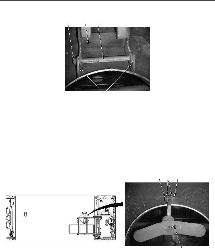
Figure 4. Manhole Cover and Bracket Removal.
NOTE
Note position of hinge prior to removal.
7.
Remove shaft hinge (Figure 4, Item 9) and manhole cover bracket (Figure 4, Item 3) from two brackets (Figure
4, Item 10).
NOTE
Perform Step (8) if manhole cover hold down assembly is damaged.
8.
Remove locknut (Figure 5, Item 13), screw (Figure 5, Item 11), and manhole cover hold down assembly (Figure
5, Item 4) from two brackets (Figure 5, Item 12). Discard locknut.
11
12
13
4
Figure 5. Manhole Cover and Bracket Removal.
END OF TASK