
TM 5-3825-270-23&P
0166
REMOVAL - Continued
16
17, 18
19
7
20, 21
15, 22
5
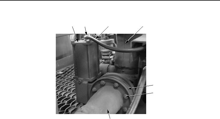
Figure 6. Flusher Nozzle Removal.
NOTE
Note position of gaskets prior to removal to ensure proper installation.
9.
Remove eight locknuts (Figure 6, Item 22), tube (Figure 6, Item 5), gasket (Figure 6, Item 20), air actuator
(Figure 6, Item 16), gasket (Figure 6, Item 21), and screws (Figure 6, Item 15) from manual water turret
assembly (figure 6, Item 7). Discard gaskets and locknuts.
10.
Repeat Steps (1) through (9) for right side.
END OF TASK
INSTALLATION
NOTE
Install gaskets as noted prior to removal.
1.
Install air actuator (Figure 7, Item 16) and tube (Figure 7, Item 5) on manual water turret assembly (Figure 7,
item 7) with gasket (Figure 7, Item 21), gasket (Figure 7, Item 20), eight screws (Figure 7, Item 15), and locknuts
(Figure 7, Item 22). Tighten screws in sequence shown.