
TM 5-3825-270-23&P
0114
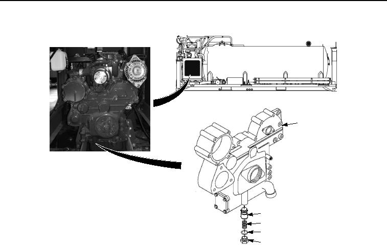
INSTALLATION - Continued
1
RADIATOR
SHOWN REMOVED
FOR CLARITY
2
3
4
5
Figure 2. Engine Gear Assembly Case Relief Valve Installation.
2.
Install preformed packing (Figure 2, Item 4) on plug (Figure 2, Item 5).
3.
Install gear assembly case relief valve (Figure 2, Item 2) in engine gear assembly case (Figure 2, Item 1).
4.
Install spring (Figure 2, Item 3) in engine gear assembly case (Figure 2, Item 1).
5.
Install plug (Figure 2, Item 5) in engine gear assembly case (Figure 2, Item 1).
END OF TASK
END OF WORK PACKAGE