
TM 5-3825-270-23&P
0113
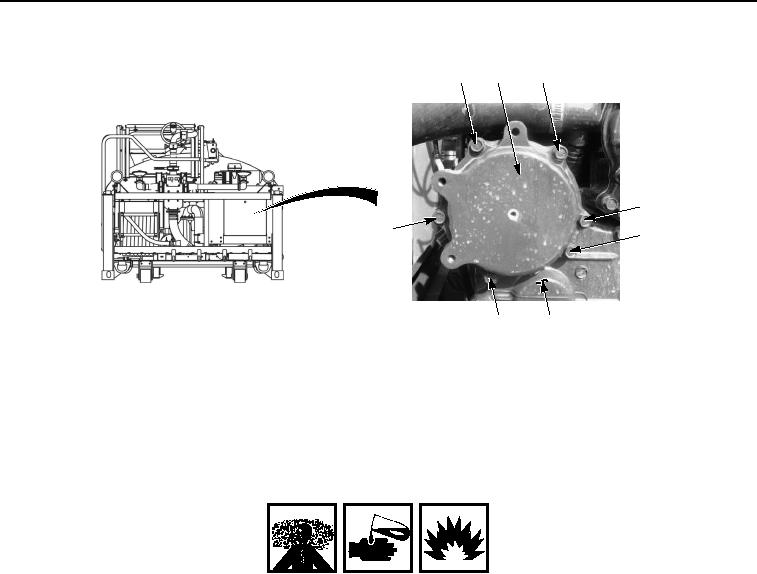
INSTALLATION - Continued
12
5, 13
12
12
12
14
8
15, 10
Figure 6. Injection Pump Gear Cover Plate Installation.
2.
Install four screws (Figure 6, Item 12) into injection pump gear cover plate (Figure 6, Item 5) and engine gear
assembly case (Figure 6, Item 15).
3.
Install screw (Figure 6, Item 8) into injection pump gear cover plate (Figure 6, Item 5) and injection pump
mounting plate (Figure 6, Item 10).
WARNING
Adhesives, solvents, and sealing compounds can burn easily, can give off harmful vapors,
and are harmful to skin and clothing. Keep away from open fire and use in well-ventilated
area. If adhesive, solvent, or sealing compound gets on skin or clothing, wash immediately
with soap and water. Failure to comply may result in injury or death to personnel.
NOTE
Perform Steps (4) and (5) if fitting was removed.
4.
Apply sealant to the threads of fitting (Figure 7, Item 4).