
TM 5-3825-270-23&P
0100
INSTALLATION - Continued
2
3
1
WIRE
10
10
10
WIRE
15
15
5
20
20
1
4
6
5
WIRE
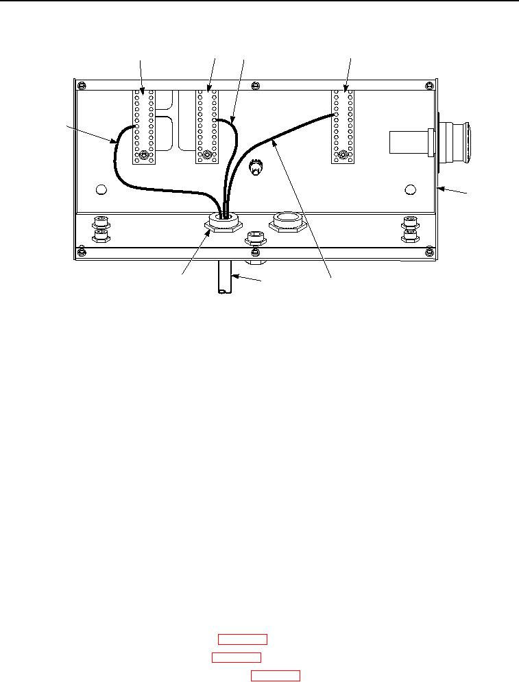
Figure 20. Engine Wire Harness Installation.
42.
Install white wire on interconnect terminal strip (Figure 20, Item 3) socket 20.
43.
Remove white wire on negative terminal strip (Figure 20, Item 2) socket 10.
44.
Remove white wire on interconnect terminal strip (Figure 20, Item 3) socket 7.
45.
Remove white wire on interconnect terminal strip (Figure 20, Item 3) socket 5.
46.
Remove white wire on interconnect terminal strip (Figure 20, Item 3) socket 3.
47.
Remove black wire on interconnect terminal strip (Figure 20, Item 3) socket 14.
48.
Remove black wire on interconnect terminal strip (Figure 20, Item 3) socket 11.
49.
Remove black wire on interconnect terminal strip (Figure 20, Item 3) socket 10.
50.
Remove black wire on positive terminal strip (Figure 20, Item 1) socket 19.
51.
Remove black wire on interconnect terminal strip (Figure 20, Item 3) socket 6.
52.
Remove black wire on interconnect terminal strip (Figure 20, Item 3) socket 4.
53.
Remove black wire on interconnect terminal strip (Figure 20, Item 3) socket 2.
54.
Remove black wire on interconnect terminal strip (Figure 20, Item 3) socket 1.
55.
Install white wire on positive terminal strip (Figure 20, Item 1) socket 10.
END OF TASK
FOLLOW-ON MAINTENANCE
1.
Install water pump outlet gauge and hose. (WP 0179)
2.
Install water pump inlet gauge and hose. (WP 0178)
3.
Install main control panel 15 AMP circuit breaker. (WP 0078)