
TM 5-3825-270-23&P
0100
INSTALLATION - Continued
11.
Install green wire on negative terminal strip (Figure 16, Item 2) socket 8.
12.
Install white wire on interconnect terminal strip (Figure 16, Item 3) socket 15.
13.
Install black wire on negative terminal strip (Figure 16, Item 2) socket 9.
14.
Install red wire on interconnect terminal strip (Figure 16 , Item 3) socket 13.
NOTE
Perform Steps (15) through (17) work light harness.
15.
Install work light harness (Figure 17, Item 15) in main control box (Figure 17, Item 4) with retaining nut (Figure
17, Item 14).
1
2
WIRE
WIRE
10
10
10
5
15
15
1
20
20
4
14
15
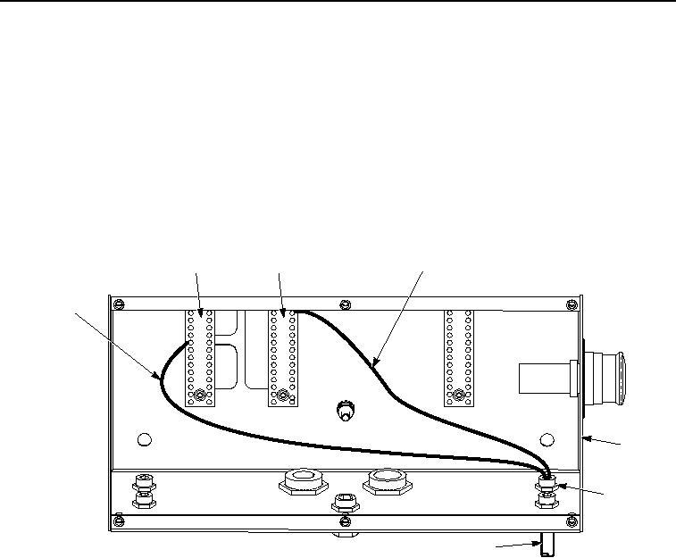
Figure 17. Work Light Wire Harness Installation.
16.
Install red wire on positive terminal strip (Figure 17, Item 1) socket 8.
17.
Install black wire on negative terminal strip (Figure 17, Item 2) socket 7.
NOTE
Perform Steps (18) through (36) for UPIK wire harness.
18.
Install UPIK wire harness (Figure 18, Item 12) in main control box (Figure 18, Item 4) with retaining nut (Figure
18, Item 13).