
TM 5-3825-270-23&P
0098
INSTALLATION - Continued
27
28, 29
30
31, 32
33
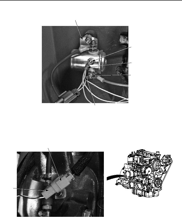
Figure 16. Engine Wire Harness Installation.
22.
Install yellow wire eyelet (Figure 16, Item 30) on glow plug relay (Figure 16, Item 27) with lockwasher (Figure
16, Item 29) and nut (Figure 16, Item 28).
23.
Connect engine timing sensor harness connector (Figure 17, Item 26) to engine wire harness connector (Figure
17, Item 25).
25
26
Figure 17. Engine Wire Harness Installation.
24.
Install wire eyelet (Figure 18, Item 22) on rear panel (Figure 18, Item 18) with lockwasher (Figure 18, Item 24)
and nut (Figure 18, Item 23).