
TM 5-3825-270-23&P
0088
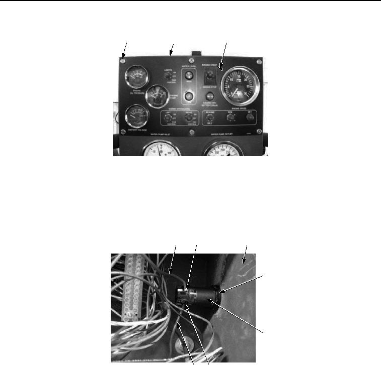
REMOVAL - Continued
5
6
3, 4
Figure 2. Main Control Panel Emergency Stop Pushbutton Removal.
NOTE
Tag and mark wires prior to removal to ensure proper installation.
3.
Remove two screws (Figure 3, Item 8) and red wires (Figure 3, Item 7) from main control panel emergency
stop pushbutton (Figure 3, Item 10).
7
8
5
9
10
7
8
Figure 3. Main Control Panel Emergency Stop Pushbutton Removal.
4.
Remove nut (Figure 3, Item 9) and main control panel emergency stop pushbutton (Figure 3, Item 10) from
main control box (Figure 3, Item 5).
END OF TASK
INSTALLATION
1.
Install main control panel emergency stop pushbutton (Figure 4, Item 10) and nut (Figure 4, Item 9) on main
control box (Figure 4, Item 5).