
TM 5-3825-270-23&P
0087
INSTALLATION - Continued
5
6
3, 4
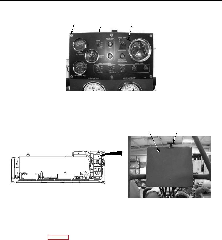
Figure 5. Main Control Panel Battery Voltage Gauge Installation.
4.
Install six washers (Figure 5, Item 4) and screws (Figure 5, Item 3) on main control box (Figure 5, Item 5) and
control panel (Figure 5, Item 6). Tighten six screws securely.
5.
Close control panel cover (Figure 6, Item 1) and secure with rubber t-handle (Figure 6, Item 2).
1
2
Figure 6. Main Control Panel Battery Voltage Gauge Installation.
END OF TASK
FOLLOW-ON MAINTENANCE
Connect batteries. (WP 0085)
END OF TASK
END OF WORK PACKAGE