
TM 5-3825-270-23&P
FIELD MAINTENANCE
CONTROL PANEL LIGHT SWITCH REPLACEMENT
INITIAL SETUP:
Tools and Special Tools
References
Tool Kit, General Mechanic's: Automotive
Parts Manual (WP 0220) Figure 4018
(WP 0225, Table 1, Item 12)
Equipment Condition
Batteries disconnected. (WP 0085)
Materials/Parts
Compound, Sealing, Loctite 242 (WP 0224, Table
1, Item 19, 20, 21, 22)
Tags, Identification, White (WP 0224, Table 1, Item
54)
REMOVAL
1.
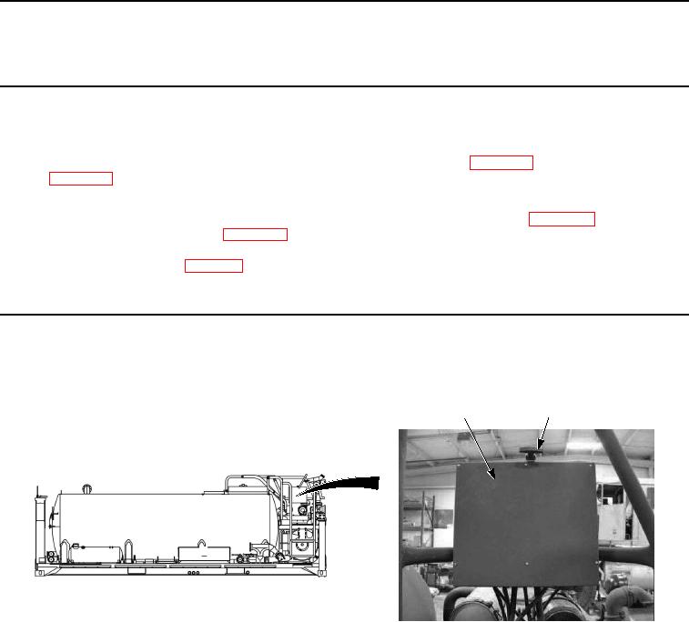
Open control panel cover (Figure 1, Item 1) by releasing rubber t-handle (Figure 1, Item 2).
1
2
Figure 1. Control Panel Light Switch Removal.
CAUTION
Do not allow control panel to hang by wires. Failure to comply may result in damage to
equipment.
2.
Remove six screws (Figure 2, Item 3) and washers (Figure 2, Item 4) from main control box (Figure 2, Item 5)
and control panel (Figure 2, Item 6).